canadian puregas equipment limited
Introduction to Nicotra Sistemi OCN-MS
Optical Cable Network Monitoring System

P.O. Box 280, 783 Hwy. 3,W., Dunnville, Ontario, N1A 2X5, Canada
Phone: 905-774-8600 Fax: 905-774-6974 E-mail info@canadianpuregas.com
www.canadianpuregas.com
1. Nicotra Sistemi OCN-MS: System Description
Nicotra Sistemi Optical Cable Monitoring System (OCN-MS) is a complete system solution which detect any anomaly on a fiber in the fastest possible way, taking care of fiber analysis, fault location and alarm notification to the proper control centers whenever is required.
It consists of:
The system carries out accurate and sophisticated OTDR measurements to evaluate the quality and availability of an optical link. Measurements on both active (ON service) fiber and spare (OFF service) fibers can be performed. Each measurement (OTDR trace) is compared to a stored reference (trace) and analyzed by means of a proper algorithm (Automatic Fault Finder - AFF).
With the help of user friendly Graphical User Interface (GUI) and OCN-MS’s open architecture, the authorized user can easily create objects, modify and save object settings both on the system tree and on Geographical Interface Systems (GIS). The monitored network elements, such as fiber, cable, and Nicotra monitoring network equipment, such as RTU, OTAU and OASI, can be created and configured on the SCU.
Nicotra OCN-MS works in the following different operating modes:
Fault mode: Where a measurement starts automatically only on a specific fiber or group of fibers after an alarm (too high BER, laser off, carrier off etc.) has been detected. The alarm can be detected by a proper unit called Optical Alarm System Interface (OASI), which is electrically connected to the transmission apparatus, or be provided by power loss at receive end and increasing of total link attenuation.
Maintenance Mode: In this mode an authorized user (Supervisor) according to a predetermined time schedule presets the automatic measurement cycle. Different measurement cycles can be set for each fiber according to the importance of the link.
On Demand Mode: At any time an authorized user can always perform a manual measurement on one or more fibers.
Continuous Mode: Once set, the continuous acquisition will be performed on the fiber. The traces will be saved and if there is any change of states the notification will be sent to the SCU.
Instrument Mode: It allows the authorized user to manually acquire and analyze fibre traces and to perform RTU control and diagnostics.
For every RTU, the manual acquisition commands have the highest privilege, the automatic acquisitions of the fault mode are followed, and then are the automatic acquisitions of the maintenance mode, and the continuous acquisitions are the last ones to be executed.
Alarms can be generated by field equipment and trace analysis. When a fault is detected the status of the related object changes and the new status will be indicated by new color of the related object symbols shown both in the system tree and on the geographical map. Acoustic and visual signal can be also obtained. An internal application is available for alarm viewing and acknowledge.
Once alarm occurs, the alarm notification will be sent immediately to operators in the following ways: Pager, GSM mobile phone, E-mail and fax. At the same time a report will be generated automatically on local or remote printer providing detailed information about fibres and measurement.
The following functions are provided for OCN-MS system administration:
A careful distribution of the user’s profile will guarantee the OCN-MS system security. The following user’s profiles are available:
Superuser (S)
Different permissions are distributed to each user’s profile. Users with Superuse (S) profile are enabled to access the whole system without any restriction, and users with Viewer (V) profile can view the system state but cannot perform any setting operation. The user login is also protected by user password.
The RTUs perform automatic and manual measurement and automatic fault location. The setup, activation and analysis of the measurements and fault location can be carried out either on the SCU or on the RTU. The full access and control of the RTU are provided on the SCU. The automatic time synchronization and the remote boot command are available.
A remote PC can be connected over PSTN or TCP/IP for accessing the RTU. This feature is implemented for measurements during network construction.
The OCN-MS web portal features include system access from any networked computer, an OCN-MS browser for quick access to monitored components, a summary of monitored fiber status and a complete view of all scheduled tasks. Additional web portal features allow for easy viewing of network status and alarm history, as well as easy to read status and configuration reports.
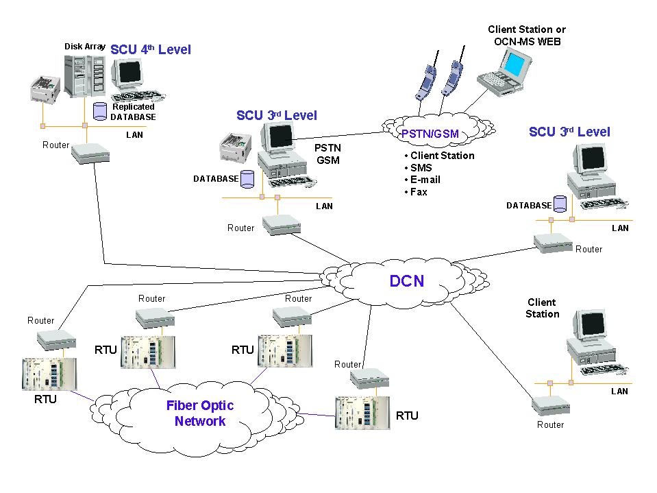
The OCN-MS architecture is subdivided in four levels according to the following picture:
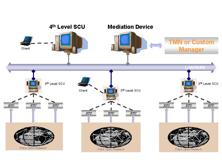
The first level is represented by the fiber network to be monitored. The second level consists of the whole set of measurement equipment. The third/fourth levels are the SCU (Supervisory Control Unit). The third levels, named 3rd SCU, are district/regional control unit, and the fourth levels, named 4th SCU, are central/national control unit. These machines are powerful stations, PC based operating under Windows2000, and different PC architecture including redundant data storage can be provided. A UNIX machine can be provided acting as a gateway to the TMN upper hierarchy. Nicotra provides the TMN agent, which supports communication of a Q3 interface for the customer TMN manager. Otherwise a SNMP Agent can be implemented on the same 4th level SCU.
The communication among SCUs and RTUs is supported on PSTN, DDN, X.25 and other protocols as detailed in the following picture. The protocol used in the virtual LAN, on Nicotra side, is TCP/IP.
Other interface to high layer and complementary system can be implemented with:
To implement the system functionality, a powerful software package has been developed. It can be divided in the following functional blocks:
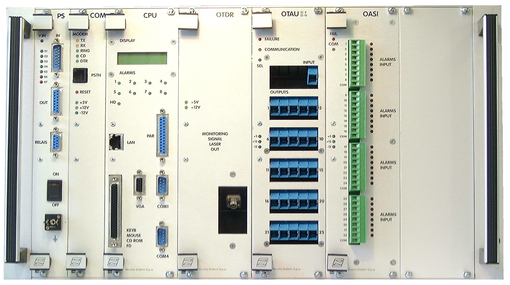
The Nicotra Remote Test Unit (RTU) includes in a 6U 19" modular standard rack all the components requested to perform fiber optic monitoring. (ETSI version is also available on request).
BASIC unit
Including typically: PS, COM, CPU, OTDR, OTAU module and OASI module as requested.
REMOTE unit
Including typically: PS, COM, OTAU module (optically controlled) and OASI module as requested.
The expansion unit can be provided together with the above units to provide additional slots for housing typically PS and OTAU module or OASI module as requested. Connection to BASIC/ REMOTE unit is performed by RS-485.
The basic unit is composed of the following modules:
The remote RTU is composed by the following modules:
The remote RTU does not contain the OTDR module and is used to distribute the optical signal to the fibers. It collects the monitoring signal from an incoming fiber and distributes it through output ports to the fibers to be monitored.
The deployment of the remote unit for distribution network monitoring becomes really useful and cost effective as the cables length are limited and the number of fibers to be monitored are huge. In these cases, designing a monitoring project is useful to reduce the number of OTDR modules and then reduce the monitoring system budget.
This module with a microprocessor managing all the unit functions, represents the heart of the monitoring system.
It can be programmed to perform single real-time measurement ("on demand measure") and periodical scanning of selected sets of fibers, choosing for each individual fiber all the measurement parameters.
This Unit has been designed to guarantee an high degree of flexibility, expandability and to permit easy maintenance and upgrading operations.
The Controller is equipped with a standard IEEE 802.3 network adapter for communication with the SCU.
The communication module makes available a Modem of 33.6 Kbps for connection via PSTN. It is supplied on specific request.
Normally, the RTU connection with the SCU is made through the Ethernet interface of CPU controller module, and for this reason the communication module is not usually supplied.
The RTU is provided with a power supply module, which supplies all the modules housed in the rack. The power supply module is available in 48 V DC input.
The OTDR module consists of a module that is plugged-in the RTU rack. The OTDR modules can be selected among the following options:
This module is equipped with an optical switch for connecting the OTDR output to monitored fibers. In its standard configuration, the OTAU has the number of ports ranges available from 4 to 25.
On request the OTAU module can be equipped with up to 100 ports.
To meet the required capacity more than one OTAU can be used and connected in a cascade mode so that, in principle an unlimited connection capacity can be achieved.
The Nicotra OTAU is available in two versions:
The use of the OTAU/O modules, allow installing remote RTU in the field and distributing the monitoring signal to the whole optical network that needs to be monitored with high cost effective impact. The control of these OTAU/O, made in an "optical way" and without need of modems or other network communication devices, gives great advantages in speed, reliability and, overall, in global system performances.
This module is used to collect the alarms from the transmission equipment alarm panels in order to start the monitoring on a fiber after an abnormal condition is detected.
Examples of alarms suitable to be monitored are: BER level, transmission equipment power supply failure, carrier off, laser off etc.
The OASI module is available with 32-alarm input port in its standard configuration.
This rack is supplied only when the customers want to monitor "ON service" fibers. Similar rack can be supplied for field installation (outside the RTU).
The WDM rack is a separate dedicated 19" 3U rack and it contains up to 20 sub-modules.
These sub-modules are passive optical components such as:
The connections from the monitoring units (RTU) to the fibers are obtained by means of passive components (patch cords, WDM..) according to the following scheme:
Additional passive components, named stop band filters, are inserted to prevent the monitoring signal reaching the customer transmission apparatus receiver. The number and types of WDM and filters, depend basically on two parameters:
Inside the RTU a stop band filter is inserted to prevent the transmission signal reaching the OTDR receiver.
Back to Canadian Puregas home page | E-mail Canadian Puregas