 canadian puregas equipment limited
Introduction to Nicotra Sistemi SpA NiDA2 System

P.O. Box 280, 783 Hwy. 3,W., Dunnville, Ontario, N1A 2X5, Canada
Phone: 905-774-8600 Fax: 905-774-6974 E-mail info@canadianpuregas.com
www.canadianpuregas.com
Table of Contents
1 Introduction *
2 General Description *
2.1 System Architecture *
2.2 System’s Main Functionalities *
2.2.1 Pressurized Copper Cable Monitoring *
2.2.2 Common Characteristics *
2.3 SCU Characteristics *
2.3.1 Information Base *
2.3.1.1 Network Objects *
2.3.1.2 Monitoring System Objects *
2.3.2 Object Status Mapping and Alarm Generation Rules *
2.3.3 Logging *
2.3.3.1 Event Log *
2.3.3.2 Alarm Log *
2.3.3.3 Task Log *
2.3.3.4 Historical Log *
2.3.4 Data Distribution and Access *
2.3.5 Fault Tolerance *
2.3.6 Data Base Administration *
2.3.7 User Interface *
2.3.7.1 General Functionalities *
2.3.7.2 Taskbar *
2.3.7.3 Console Manager *
2.3.7.4 Schema Manager *
2.3.7.5 Alarm Log *
2.3.7.6 Task Log *
2.3.7.7 Event Log *
2.3.7.8 Pressurized Cable Monitoring-Data Representation *
2.3.7.9 Event Location *
2.3.7.10 GIS *
2.3.7.11 Pressurized Cable Monitoring-Synoptic *
2.3.8 Tools and Configuration Utilities *
2.3.8.1 Backup/Restore *
2.3.8.2 Communication Configuration *
2.3.8.3 Symbol Library Editing/Upgrading *
2.3.8.4 Pressurized Cable Monitoring-Units *
2.3.8.5 Pressurized Cable Monitoring-Alarm Thresholds *
2.3.9 Customisation *
2.3.9.1 Default Values Definition. *
2.3.9.2 Alarm Report *
2.3.10 Operating System and DB Engine *
2.4 Remote Test Unit Characteristics *
2.4.1 Generalities *
2.4.2 RTU Types *
2.4.2.1 SEC800 *
2.4.2.1.1 Generalities *
2.4.2.1.2 Main Characteristics *
2.4.2.1.3 Specific Characteristics *
2.4.2.2 MiniSEC *
2.4.2.2.1 Generalities *
2.4.2.2.2 Main Characteristics *
2.4.2.2.3 Specific Characteristics *
2.4.2.3 MiniDAS *
2.4.2.4 DAS800 *
2.4.3 AirDryers *
2.4.3.1 Description *
2.4.3.2 Main Characteristics *
3 NiDA2 System: Examples of System Configuration *
3.1 Distributed Database Configuration *
3.2 Client-Server Configuration *
Table of Figures
Fig. 1: NiDA2 Architecture *
Fig. 2: Distributed Database Configuration *
Fig. 3: Client-Server Configuration *
Fig. 4: Client-Server Configuration with Server Backup *
- Introduction
Scope of this document is to introduce Nicotra Sistemi SpA NiDA2 system: the new version of the well-known NiDA system for pressurized copper cable network monitoring.
In particular, Nicotra Sistemi SpA would like to give a clear and complete vision of NiDA2 system architecture highlighting characteristic features and possible system implementations.
System Architecture
In the following figure (Fig. 1: NiDA2 Architecture) is described the proposed Nicotra solution for Pressurized Copper Cable Monitoring and Security Management:
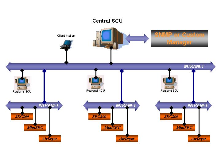
- NiDA2 Architecture
Nicotra proposal foresees the following elements:
- Control and Management Centre (SCU): at this level are performed the system management tasks, the data storing and system configuration. Three different SCU types are present in the system:
- Central SCU: this is a PC based workstation generally installed at central office, where all the information regarding the current state of monitored network and the monitoring system are available. The DB residing at this level is constantly and automatically aligned with Regional DBs. An operator, working at the Central station, has the full control of the whole system. Alignment between the system DB (virtual system) and the managed network and components (field) is automatic and works in unattended mode;
- Regional SCU: this workstations manage only a particular sub network, or sub area receiving measurements and alarms from Nicotra Sistemi SpA Acquisition Units (SEC800, MiniSEC), analysing the incoming data, keeping aligned their DBs with the Central station one and dispatching alarms to proper terminals. The DB replication mechanism requires that the communication channel linking each Regional SCU and the Central SCU is on Intranet: therefore a TCP/IP based network is required;
- Clients: these are PC based workstation, connected as DB Clients to the SCU DB. This Client stations are normally deployed at copper cable maintenance office. The operators can perform all the operations on the system, working at Client level. The connection between Clients and the system DB can be either via PSTN or LAN/WAN;
- Acquisition Units and AirDryers (hereafter refer to as Remote Test Unit (RTU)):
- MiniSEC and SEC800: these are Nicotra acquisition units that are able to acquire measurement from the pressurized copper network. Communication interfaces available from MiniSEC and SEC800 are either via PSTN (Modem 56kbps) or via Intranet supporting TCP/IP protocol.
- Canadian Puregas Air Dryers provide the capability of full integration in the NiDA2 monitoring and management system. They can be montored by installing a discrete alarm board.
- Sensors: Nicotra Sistemi SpA sensors can be grouped in two main families:
- Pressurization Monitoring Sensors: these are the standard Nicotra Sistemi SpA Remote Addressable Devices (RADs) such as: Pressure Transducers (TP204M), Air Flow (RAD TFL micro), Humidity Transducers (RAD RHLM micro, and RHWM micro), …All these transducers work according to sequential answer and conversion of measured value to frequency (1000-2000Hz);
- Security Sensors: MHS for Man Hole Security and Opening management, ACS for Aerial Cable Security. These transducers are designed for special security applications and provide fast response on alarm detection (i.e.: 127 transducers connected to a single pair are acquired in 6 seconds).
- System’s Main Functionalities
Hereafter are listed the main functionalities of Nicotra NiDA2 software:
Pressurized Copper Cable Monitoring
- The system monitors the state of copper pressurized cables for telecommunication by means of acquiring data concerning pressure and by analysing this information in order to localize an eventual leak point;
- Leak point position is displayed using the either a schematic (synoptic) and the GIS interfaces;
- The system is also equipped with proper transducers in order to measure other important operational condition relevant to cable pressurization (relative humidity and airflow) as far as general operating conditions such as room and device temperature, and water presence;
- The system is able to monitor alarm condition in Nicotra Sistemi SpA or third part devices by means of proper alarm contacts that can collect ON/OFF signals from equipment alarm interfaces;
- The system can collect operational data directly from AirDryers;
- Measurements are performed by transducers positioned along network cables or in customer-defined locations and sent to the RTU as frequency modulated signals;
- Comparison between alarm thresholds and current measures are performed directly at RTU level.
- Common Characteristics
- Transducers (TP and RAD), and security sensors are fed through the same transmission line (copper pair) used for measurement data transmission;
- Each transducer or sensor has a uniquely identified address;
- In case of alarm generation the system provides the propagation of the alarm notification to all the concerned Clients and prints the predefined alarm reports. Historical log of the received alarms is kept at SCU site.
- The system provide the mean for alarm dispatching to several terminal such as:
- E-mail addresses;
- SMS to GSM mobile phones;
- Pagers;
- Alarm dispatching is fully configurable according to several parameters such territorial competence, administrative competence, user profile, working hours (working days, holidays, 24 hours services, etc.);
- An automatic procedure is constantly keeping aligned the central DB with the Regional DBs.
- In case of Regional SCU fault, the system administrator will be informed and a "Fault tolerance" semiautomatic procedure will start to switch the system control from the faulty Regional SCU to the central SCU: in this case the Central SCU is acting directly as supervisory and management center for all the RTUs and cables belonging to the sub-network controlled by the faulty Regional SCU;
- Using a client workstation connected to the SCU DB, it is possible to completely configure and manage the system, schedule measurements and data collection, define thresholds, visualize collected data and locate faults and leaks;
- The user interface to the system is easy to understand, is mainly graphical and supports geographical interface facilities (GIS);
- Different degrees of system access (profiles) are available; user rights are depending on specific profile assigned, control is based on password. Each user can access only to his own specific sub network/area;
- NiDA2 software is multitasking;
- The system may provide full access to alarm data using an SNMP agent;
- The system may be customized in order to be interfaced to higher level management system according to the various TELECOM requirements;
- The application software includes the HELP on line.
- SCU Characteristics
- Information Base
The Information Base contains all the data needed to create a virtual representation of the system; once a user gains access to this information base he is able to run and interact with the system (or the subsystem concerned) with no need of any other source of data.
The objects are divided into two separate branches:
- Network Description: all the objects required to describe the topology of the customer telecom network, including geographical references;
- Monitoring System: all the objects required to describe the Nicotra Sistemi SpA monitoring system and to store and retrieve the information about the historical and running measurement/alarms,
The database structure is compatible with an Object Oriented Description and allows MIB mapping for TMN, SNMP or custom Agent applications.
- Network Objects
- Node: Significant locations along the physical network (e.g.: exchange);
- Device: Significant elements of the network (e.g.: joint, ect.);
- Segment: A homogeneous portion of telecom network between two joints;
- Cable: Any user defined collection of segments. Its main use should be to group together logically linked segments in order to propagate alarm conditions and enhance network topology visibility;
- Pneumatic Route: Any user defined collection of segments sharing the same airflow and realizing a point-to-point connection. Its main use should be to group together pneumatically linked segments in order to show pressure and flux profiles and to compute leak locations.
- Monitoring System Objects
- SCU: The Supervisor Control Unit is a subsystem responsible of collecting data from RTUs, storing, processing them and generating alarm notification and appropriate user interface;
- RTU: The Remote Test Unit is a subsystem capable of collecting, pre-processing and sending data coming from the field sensors to the SCU. The RTU may receive data from its sensors in many different ways, although the most common is using a dedicated board that collects data from several transducers/sensors lines (usually copper pairs) on which are connected (usually up to 127) remote transducers/sensors;
- BOARD: Main subcomponent of a RTU (e.g.: SEC800 TPM1 board, ALM1 alarm board, etc.);
- TRASDUCER/SENSOR: Devices that collect data/alarm from the field (pressure, air flow, relative humidity, etc.) and make them available to the system.
For each object all the parameters needed for configuration, as well as the status information are stored in the system database.
For what concerns the sensor, an historical storage for the values read is provided, along with all the procedure to back-up and retrieve historical data.
A similar historical storage is provided for alarm history and log-in/log-out operations (for administrative and safety purposes).
All the data needed to provide the geographical interface (file containing the maps excluded) is stored in the same system database as the system and network information.
- Object Status Mapping and Alarm Generation Rules
Each alarm generated by any system and network element is classified in one of the following six severity categories:
- Critical: Indicates that a service affecting condition has occurred and immediate corrective action is required. Such a severity is used when the managed entity is totally out of service and its capability must be restored;
- Major: Indicates that a service affecting condition has occurred and urgent corrective action is required. Such a severity is used when there is a severe degradation in the capability of the managed entity and its full capability must be restored;
- Minor: Indicates that a non-service affecting condition has occurred and that corrective action should be taken in order to prevent a more serious fault;
- Warning: Indicates the detection of a potential or impending service affecting fault, before any significant effects have been felt;
- Indeterminate: Indicates that the severity level cannot be determined;
- Cleared: Indicates the clearing of one or more previously reported alarms.
Alarms are generated when an object state change occurs; the rules for alarm generation (i.e. which state transitions shall generate an alarm) are configured at system level.
Changes in state of an object may be generated by:
- A measurement value exceeding a pre-defined absolute threshold;
- A system diagnostic message (like "Air Dryer Power failure" or "Database initialisation failure");
- A state propagation mechanism;
An independent storage for a management state for RTU, Board, Sensor and Cable is provided.
Management State may assume one of the following values:
- In service (operational);
- Out of service;
- Construction;
- Maintenance;
It is possible for the operator to flag an object management state as operational or under construction, resulting in all events relating to the object to be classified accordingly.
New objects are by default flagged as under construction until marked operational by the operator.
This shall prevent a flood of events during the installation process as well as during the creation of new services.
Maintenance status has to be scheduled, providing a "start time" and a "duration". When Maintenance time for that object expires and the object is still in Maintenance state, a specific alarm is generated.
Logging
The following logs are available:
- Event Log;
- Alarm Log;
- Task Log.
- Event Log
This log traces events under all of the following circumstances:
- When user logs in and out;
- When any manual or automatic corrective action occurs (e.g.: RTU database reconfiguration, etc.);
- When any failure in communication with other SCUs or RTUs occurs.
- Alarm Log
All the alarms generated by any pressurization-monitoring acquisition units are recorded in the Alarm Log, together with the alarm clearance.
The Alarm Log reports for each alarm:
- Object name and identifiers;
- State;
- State message;
- Management State;
- Alarm type (New - Cleared);
- Time of alarm generation/clearance;
- Identity of the operator that acknowledged the alarm (if any);
- Time of acknowledge;
- Notes (user edited).
- Task Log
A Task Log entry is generated any time the system requires to communicate with the RTUs or vice versa.
The Task Log reports:
- Object concerned with the action;
- Action type;
- State of the action;
- Priority of the action;
- Number of retry to be executed before considering failed the action;
- User requiring the action;
- Time of action submission;
- Time of action closure.
- Historical Log
- Each log has a FIFO structure, with limited number of records allowed.
- Log capacity is user configurable.
- When the defined capacity is exceeded an automatic procedure transfers old log records to one or more historical log(s).
- Historical log capacity is user configurable.
- When this capacity is next to be exceeded (80%) the user is warned and a mass storage archiving facility is provided.
- Procedures to manually re-load and re-download historical records from and to mass storage devices is provided.
Data Distribution and Access
The system database containing data relevant to pressurization monitoring is stored at Regional level, every change in this database, reflecting a modification of the real system (e.g.: pressure exceeding a predefined lower threshold, etc.), is automatically replicated on the Central SCU database. The automatic database replication is performed by a set of DB procedures running on Regional SCUs and at Central SCU.
For operational purposes the user can access the system DB using a Client workstation that can be located anywhere a suitable communication channel is available: both PSTN and LAN/WAN link are suitable for the above specified DB connection.
Fault Tolerance
In case of Regional SCU malfunctions, the operator working at Central station is automatically informed, a semiautomatic Fault Tolerance procedure starts and the Central SCU will start managing the sub-network elements formerly controlled by the faulty Regional SCU.
Data Base Administration
It is possible to perform all of the following administrative functions:
- Back-up of system and database on removable storage medium located at the SCU. Back-up is automatically or manually performed according to system administrator choice;
- Restore of system and database;
- System shutdown;
- System rebooting;
For what concerns user access to the information base and to the system the application manages the following user rights, and allows the creation and configuration of user profiles with any combination of the available rights:
- System Administrator: Create/delete/edit user profiles by choosing among available rights, Create/delete/edit a user with assignment of a name, password and profile;
- System Programmer: Create/delete/edit system and network elements, add and assign RTUs, setting up cables and pneumatic routes, design automatic measures, setting up security sensor location;
- Backup & purge: backup measures and purge them from the current database.
- Acquire measures: stimulate new data acquisition from the field;
- Alarm Acknowledge;
- View: Read only access to the database;
Each User Profile and User list of rights applies only to the part of the network and application (pressurization monitoring or security management) defined by the system administrator.
User Interface
General Functionalities
Two types of user interface are implemented: Schematic and Geographic.
Schematic Interface is a typical GUI that includes graphic controls typical of a window environment (i.e. tables, dialog boxes, lists controls, graphs, grids).
Geographic Interface means GIS and Synoptic.
Access to all the applications is restricted according to user profile.
Common user interface includes a Taskbar and a main application grouping basic functions.
Main applications will be referred to as Console Manager.
Modules performing basic functions are listed below:
- Taskbar;
- Console Manager;
- Schema Manager;
- Event Log;
- Alarm Log;
- Message Log;
- Geographical Interface (GIS/Map/Synoptic);
- Data Representation (x-y chart);
- Pressurization Data Analysis (Leak Location);
- Security Alarm Analysis (Alarm Site);
- Tools and Configuration Utility.
All the listed modules are accessible from taskbar or Console Manager.
- Taskbar
Taskbar is always shown on the screen or AutoHide.
Taskbar performs the following functions:
- Applications invoking (or focusing);
- Overall system and network state display (show if there is any unacknowledged alarm running, only acknowledged alarm or no alarm at all etc.);
- The taskbar is configurable.
- Console Manager
The Console manager is a GUI application including:
- Menus;
- Toolbars;
- Online Help;
- A framework including:
- Schema Manager view windows;
- Task Log window;
- Alarm Log window;
Console Manager allows the user to invoke the other modules of the user interface, eventually passing relevant parameters to identify the object data to be displayed.
- Schema Manager
The Schema Manager represents the hierarchic tree of system and network objects.
Hierarchic tree is a Tree View control.
Each object is represented with a colour depending on its up-to-date state.
The Schema Manager allows the user to configure, insert or delete any object of the system and network.
Right Mouse clicking on any object inside the Tree View Control invokes the available actions for that object.
Basic actions for all objects are:
- Hierarchical level Navigation;
- Object relations view;
- Invoke a dialog or tabbed dialog box performing the database access functions (insert, delete, select, update). These dialogs includes the following functions:
- Default values setting;
- Range checking;
- Data consistency;
- GIS focusing selecting best layer and map to represent selected object and object highlighting;
- Data Representation focusing and Leak Location and Alarm Site computing;
- Pressurized Cables Automatic Synoptic generation;
- Print and/or preview of configuration report;
- Print and/or preview of alarm and measurement report.
The application allows the user to choose the mechanism to initiate the configuration parameters transfer from the SCU to the RTU.
The following mechanisms are available: configuration transfer at programming session closure: when the user closes the programming session the application warns the user, using a proper dialog box, that the information base has been modified and the user is allowed to confirm or abort the configuration transfer.
The authorized user is allowed to set the management state of a RTU, a board a generic sensor or a cable.
Maximum time for the object to stay in maintenance time is user definable and does not exceed a predefined time different for each object.
When the maintenance state time is exceeded a "Maintenance overtime" alarm is generated.
The user is allowed to:
- Display for each object its management state;
- Filter the alarms display on a management state criteria;
- Filter the alarms generation on a management state criteria;
- Discard new measures on object in a specific management state.
- Alarm Log
The Alarm Log window is a control always up-to-date reporting all the state transitions of system and network objects. All the information useful to identify the transition type and the object concerned with the transition are reported.
Following functions are available.
- Sorting/Filtering on any combination of following criteria:
- Date;
- Object hierarchy;
- Object state;
- Alarm acknowledgement;
- Configuration and alarm Report generation;
- Link to GIS (focus to GIS application, object in alarm highlighting);
- Link to Data Display and Leak Location applications.
- Task Log
The Task Log window is a control always up-to-date reporting all the state of operations between SCU and RTU.
Operations managed are:
- Call from SCU to RTU to download a scheduled measure (Automatic Cycle mode);
- Call from RTU to SCU on alarm notification for pressurization monitoring or for security management;
- Call from SCU to RTU to acquire new data or transfer configuration information (On Demand mode);
The following functions are implemented:
- Disable calls to a specific RTU;
- Delete/abort specific calls;
- Sorting/filtering on date and object hierarchy or state;
- Operation reports generation.
- Event Log
The Event Log tabbed window is a control reporting all the application messages in the system logs.
Main categories of messages are:
- Diagnostic messages generated by applications;
- Login/Logout to the applications (user, profile, login and logout time).
Each Log implements the following functions:
- Disable;
- Export to text file;
- Print;
- Delete;
- Set storage maximum dimension (number of records/messages);
- Set display maximum dimension (number of records/messages).
- Pressurized Cable Monitoring-Data Representation
Data Representation is an application that reports on the screen an x-y graph, showing pressure vs. distance, airflow vs. distance or air flow/pressure vs. distance profiles.
Each profile logically groups a set of sensors (i.e. sensors on a pneumatic route or on a segment).
Usually on x-axes is reported the distance of the sensor from the beginning of the first segment and on y-axes the value associated with the sensor (usually pressure or air flow).
The following functions are available:
- Multiple historical profiles representation;
- Selection of the set of profiles to be displayed;
- Selection of the sensors to be displayed among the available sensors;
- Invoking and configuring the parameters of the Leak Location module;
- Graphical Display of the leak location results;
- Profile(s) Report generation;
- Setting and storing of reference profiles.
The window containing the graph supports interaction with the user: clicking on the point referring to a sensor the user has access to the related data in the information base.
- Event Location
Leak Location is a library containing the algorithms for locating a leak using pressure and flux data on the cable.
The library is designed to be easy upgradeable with new algorithms.
The following algorithms are implemented:
- Standard NiDA 1.xx Nicotra;
- Normalized NiDA 1.xx Nicotra,
The Leak Location calculation can be performed automatically on alarm reception: the user can configure the automatic calculation.
- GIS
GIS (Geographical Interface System) is the part of the user interface that provides means of referring geographically with GPS coordinates all the physical objects and event in the network and monitoring system.
The following functions are implemented:
- Basic graphic functions and parameters:
- Line draw (type, thickness, colour)
- Text (colour, font, size, tilt)
- Circle/ellipsis draw (colour, type)
- Insert object from library
- Graphic symbol library for purely graphic objects (manhole, cable, …) and active System object (SCU, RTU, pressure sensors, security sensors, …);
- Graphic tool for editing/creating symbols in library;
- Multiple layer definition;
- For each graphical layer it is possible to define:
- Background image (raster/vectorial);
- Enable/disable object display;
- Layer parameters (Object scale, object colour);
- Geographical calibration parameters via a specific tool/wizard;
- GPS units selection;
- Image/blank background selection;
- Default layer selection;
- Layout definition (state - colour association);
- Layer Navigation (Pan, Zoom with automatic selection of best layer, object - layer association);
- Management state setting of an RTU, a sensor, cable or device by an authorized user;
- Measuring tool (for lines, paths or surfaces);
- Real time representation of object state (using colour attribute);
- Real time representation of last measure for each sensor;
- Real time representation of security alarms;
- Real time representation of faults;
- Invoke a dialog or tabbed dialog box performing the database access functions (insert, delete, select, update). These dialogs includes the following functions:
- Default values setting;
- Range checking;
- Data consistency;
- Data Representation focusing and Leak Location computing;
- Automatic Synoptic generation;
- Print and/or preview of configuration report.
- Pressurized Cable Monitoring-Synoptic
Synoptic is a module that automatically generates a graphical representation of a specified Pneumatic Route.
Synoptic shows each object properly connected, labelled and with a colour-state association.
The following self-generating representations are available:
- All the objects inside a node (e.g.: all cable in the same duct);
- All segments, nodes and sensors involved in a pneumatic route;
- All the objects inside an RTU.
- Tools and Configuration Utilities
- Backup/Restore
The following functions are provided:
- Full database backup/restore;
- Backup/restore supporting of different units (DAT, CDROM…);
- Automatic backup with user defined frequency;
- Restore to a database different (but compatible) from the source one;
- Communication Configuration
All communication parameters (ports, initialisation strings etc.) for both PSTN and TCP/IP Intranet are entered using dialogs.
- Symbol Library Editing/Upgrading
A tool for creation or editing of system and graphical symbols is available (see GIS specifications).
- Pressurized Cable Monitoring-Units
The application accepts all the units in the International US/British standard.
The user performs unit selection with a dialog without editing directly configuration files.
- Pressurized Cable Monitoring-Alarm Thresholds
Pressure measurements can be selected according to absolute measures (as carried out by pressure transducers) or to relative pressure (referred to reference measure/value).
Alarm thresholds are programmable, for all sensors, air dryers and alarm contacts.
Two types of Thresholds can be set:
- Inferior1 (warning) and Inferior2 (alarm): when the measured value is below the inferior1/inferior2 threshold a warning/alarm is generated;
- Superior1 (warning) and Superior2 (alarm): when the measured value is above the superior1/superior2 threshold a warning/alarm is generated;
Both the Inferior and the Superior thresholds can be set in the following ways:
- Absolute;
- Percentage of the current value.
- Customisation
- Default Values Definition.
Default values for any object property are user definable.
- Alarm Report
Alarm report customisation at user level can be provided on customer request.
Properties to be customized for alarm and or diagnostics reports:
- Report layout;
- Report generation rules.
- Operating System and DB Engine
Nicotra Sistemi SpA NiDA2 system runs in Windows2000 environment: this is the OS at Central SCU, Regional SCU and Client Stations.
For what concern the DB Engine, Nicotra Sistemi SpA has selected Oracle8 a standard solution that guarantees the required reliability and worldwide support.
Remote Test Unit Characteristics
- Generalities
The RTUs perform the monitoring of transducers belonging to Pressurized Copper Cable Network.
RTU Types
Two RTU families are available from Nicotra:
- The traditional line composed of MiniDAS and DAS800;
- The new line composed of MiniSEC and SEC800 that provide all the new functionalities (i.e.: Intranet connectivity, modularity (for SEC800)) requested by Telecom companies.
The next paragraphs illustrate the main characteristics of MiniSEC and SEC800. For more detailed information on these units and for MiniDAS and DAS800 characteristics please refer to the specific data sheet or manuals.
- SEC800
- Generalities
SEC800 is the latest Acquisition Unit designed by Nicotra to meet the customer needs in copper cable pressure monitoring.
The SEC800 can acquire the transducer measurements faster than ever. Each acquisition card acquires two transducer lines simultaneously.
It automatically acquires the measures from the RADs (Remote Addressable Transducers), and it transmits the alarms to the Supervisory Station using several carriers (Intranet, PSTN).
SEC800, besides the well know sequential acquisition cycle, when security sensors are used can perform fast acquisitions acquiring a complete transducer line in 6 seconds.
The SEC800 is a modular unit, standard configuration houses in a 6U 19" modular sub-rack: a Power Supply Module PSM1, a communication card COM1, the main controller card PCM1 and up to four TPM1 transducer acquisition or ALM1 alarm cards.
- Main Characteristics
- High reliability;
- No routine maintenance is required;
- Full expandability of whole functions and controlled devices;
- Signal and power supply transducer connection using the same standard telephone pair lines;
- Possibility to connect on the same input line up to 127 transducers;
- Two alarm thresholds for each TP/RAD;
- TCP/IP based LAN/WAN communication supported;
- Central Unit connection via modem 28.8Kbps V42bis using PSTN line;
- Connection capability to Nicotra Sistemi SpA electronic air dryers;
- Specific Characteristics
- Simultaneous acquisition of two remote lines each TPM1 transducer card;
- Standard sequential transducers and Fast answering transducers lines management;
- Up to 8.128 remote transducers management capability (with four TPM1 transducer card);
- Up to 128 on/off local alarms management capability (two ALM1 alarm card);
- Four free slots suitable to house transducer or alarm cards;
- Local interfacing capability: two RS422 serial lines and one RS232 serial line;
- Four dry contact relay alarm outputs.
- MiniSEC
- Generalities
The MiniSEC unit is provided with the same characteristic of larger SEC800 unit and is designed to be installed in exchanges where the expansion capability is not requested.
The MiniSEC Unit is designed as monolithic board unit and allows having an important cost reduction for small exchanges monitoring where the integration between monitoring and security is not a critical point.
The working mode is exactly the same as for the SEC800, automatically acquires the measures from the RADs/TP, and it transmits the alarms to the Supervisory Station using several carriers (Intranet, PSTN).
The MINISEC unit include in a 3U 19" modular sub-rack: power supply, communication section for PSTN and Ethernet (using TCP/IP protocol), controller unit and built-in a single acquisition section with 16 transducer lines.
- Main Characteristics
- High reliability;
- No routine maintenance is required;
- Signal and power supply transducer connection using the same standard telephone pair lines;
- Possibility to connect on the same input line up to 127 transducers (in case of ACS sensors the maximum number of sensors per line is 35);
- Two alarm thresholds for each TP/RAD;
- TCP/IP based LAN/WAN networking supported;
- Central Unit connection via modem 33.6Kbps V42bis using PSTN line;
- Connection capability to Nicotra electronic air dryers.
- Specific Characteristics
- Built-in 16 transducer lines;
- Built-in 16 on/off local alarm contacts;
- Standard sequential transducers and fast answer sensors line management;
- Up to 2.032 remote addressable transducers management capability;
- Up to 16 on/off local alarms management capability;
- Interfacing capability: two RS422 serial lines and two RS232 serial line (one used for Nicotra air dryer connection);
- Four dry contact relay alarm outputs.
- MiniDAS
Please refer to Nicotra data sheet and manuals.
- DAS800
Please refer to Nicotra data sheet and manuals.
AirDryers
Description
The latest generation of AirDryer produced by Canadian Puregas Equipment Limited has been designed to satisfy all the telephone companies requests in terms of safety, reliability, integration and maintenance.
The AirDryer operational status and alarms can be easily set and monitored by Nicotra SCU equipped with the NiDA2 software.
Thanks to its state of the art technology, the Canadian Puregas Air Dryer families provides an extraordinary long-term maintenance schedule such as:
- Major maintenance after 8000 working hours,
- Minor maintenance after 4000 working hours.
- Main Characteristics
- High reliability;
- Extra long maintenance intervals;
- Discrete alarms
- Fully integrated into Nicotra pressurization system;
- Quick and comfortable maintenance access;
- Very low operating noise level.
For further details, please refer to Canadian Puregas data sheet and manuals.
- NiDA2 System: Examples of System Configuration
The proposed system, is characterised by complete scalability and flexibility: hereafter Nicotra Sistemi SpA is pleased to submit two possible configuration of NiDA2 system, i.e.: Distributed Database Configuration and Client-Server Configuration.
Distributed Database Configuration
The following figure (Fig. 2: Distributed Database Configuration) schematically describes this system configuration:
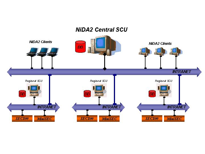
- Distributed Database Configuration
Characteristics elements of this configuration are:
- Acquisition Units: Nicotra Sistemi SpA SEC800 and MiniSEC. These units are interconnected to the SCU by means of TCP/IP based intranet;
- Regional SCU: these PC based stations are responsible for the management of defined portion of pressurized copper cable network. Each Regional SCU has a local database (Oracle8) which maps all the required information necessary for the monitoring of the managed Subnetwork;
- NiDA2 Central SCU: all the databases from Regional SCU are replicated in the Central SCU database, therefore from this PC based station, it would be possible to manage the whole pressurized copper cable network.
- NiDA2 Clients: these are PC based station, either desktop or laptop, that access remote databases stored at NiDA2 Central SCU or Regional SCU. NiDA2 Clients can be connected via Intranet or PSTN.
The Distributed Database Configuration guarantees:
- Data Redundancy: data are stored in two separated places: the NiDA2 Central SCU and the various Regional SCUs; embedded database procedures running at NiDA2 Central SCU and at Regional SCUs will assure the real time replication of data;
- SCU Fault Tolerance: in case of Regional SCU fault, NiDA2 Central SCU will directly manage the subnetwork originally controlled by the faulty Regional SCU; as soon as the faulty Regional SCU operational condition is re-established the database from NiDA2 Central SCU, relevant to the faulty Regional SCU, is automatically replicated to the regional one. On the other hand, in case of NiDA2 Central SCU fault the Regional SCUs will keep managing their own networks: as soon as NiDA2 Central SCU operational condition is re-established the databases from Regional SCUs are automatically replicated to the Central one;
- Working Load Distribution: in normal system operation the working load is distributed between Regional SCUs, therefore the use of powerful servers and of broadband communication channels between SCUs and Acquisition Units is not required.
- Client-Server Configuration
The following figure (Fig. 3: Client-Server Configuration) schematically describes this system configuration:
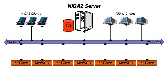
- Client-Server Configuration
Characteristics elements of this configuration are:
- Acquisition Units: Nicotra Sistemi SpA SEC800 and MiniSEC. These units are interconnected to the NiDA2 Server by means of TCP/IP based intranet;
- NiDA2 Server: this single server would be responsible for the monitoring and management of whole pressurized copper cable network. The NiDA2 Server must configured according to:
- The total number of Acquisition Units to be managed;
- The total number of pressure transducers deployed in field;
- The total number of NiDA2 Clients accessing the system.
- NiDA2 Clients: these are PC based station, either desktop or laptop, that access the remote database stored at NiDA2 Server. NiDA2 Clients can be connected via Intranet or PSTN.
The Client-Server Configuration can be enhanced in order to have full server redundancy and complete fault tolerance: these goals are achieved by means of the following (Fig. 4: Client-Server Configuration with Server Backup) architecture:
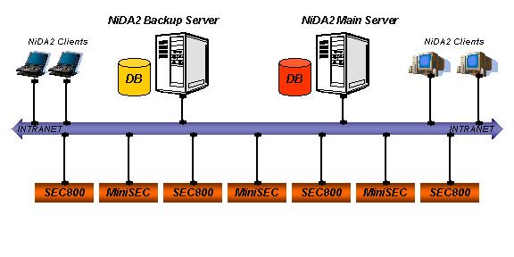
- Client-Server Configuration with Server Backup
NiDA2 Main Server, in normal system operation, acts as described above for the standard Client-Server Configuration.
A set of automatic database procedures runs on both Main and Backup servers in order to maintain the two databases (Main and Backup) aligned: in this way the Backup Server is always ready to substitute the Main Server in case of fault.
Back to Canadian Puregas home page | E-mail Canadian Puregas